Service tools and research knowledge on the selection and use of infrared heaters
Heating with infrared radiation is a complex issue. A higher emitter temperature does not always mean a faster heating. Matching the emitter and its temperature with the object to be heated (material, colour, form and surface) is absolutely crucial in infrared heating. For example, it may be that an object that perfectly absorbs a certain wave length of a certain emitter stays surprisingly cool when the same emitter is operated at a higher electric power and thus higher temperature. A change of power and temperature will always mean a shift in emitted wave lengths which, in turn, may pass through the object or be reflected.
Selection Aids
The following work guidelines give you valuable information for the correct selection of infrared heaters. While the selection according to application is solely based on practical experience, the selection according to temperature and wave length and selection according to spectra also specify the emitter-specific design parameters. The user manual include important safety and operation information.
IR Emitter Selection According to Application
| Application | Short Wave Quartz Emitters | Medium Wave Quartz Emitters | Long Wave Ceramic Infrared Emitters | ||||||||||||||||||||||||||||||||||||||||||||||||||||||||||||||||||||||||||||||||||||||||||||||||
|---|---|---|---|---|---|---|---|---|---|---|---|---|---|---|---|---|---|---|---|---|---|---|---|---|---|---|---|---|---|---|---|---|---|---|---|---|---|---|---|---|---|---|---|---|---|---|---|---|---|---|---|---|---|---|---|---|---|---|---|---|---|---|---|---|---|---|---|---|---|---|---|---|---|---|---|---|---|---|---|---|---|---|---|---|---|---|---|---|---|---|---|---|---|---|---|---|---|---|---|
| PLEASE NOTE: The allocations are indications. We strongly recommend to test possible element types and wattages before final selections are made. |
|||||||||||||||||||||||||||||||||||||||||||||||||||||||||||||||||||||||||||||||||||||||||||||||||||
| Paint drying | |||||||||||||||||||||||||||||||||||||||||||||||||||||||||||||||||||||||||||||||||||||||||||||||||||
| Steel panels - Acrylic | x | x | |||||||||||||||||||||||||||||||||||||||||||||||||||||||||||||||||||||||||||||||||||||||||||||||||
| Steel panels - Alkyd | x | x | |||||||||||||||||||||||||||||||||||||||||||||||||||||||||||||||||||||||||||||||||||||||||||||||||
| Steel panels - Epoxy | x | x | |||||||||||||||||||||||||||||||||||||||||||||||||||||||||||||||||||||||||||||||||||||||||||||||||
| Epoxy Lacquer | x | x | |||||||||||||||||||||||||||||||||||||||||||||||||||||||||||||||||||||||||||||||||||||||||||||||||
| Plastics | |||||||||||||||||||||||||||||||||||||||||||||||||||||||||||||||||||||||||||||||||||||||||||||||||||
| PVC Paste Curing | x | x | |||||||||||||||||||||||||||||||||||||||||||||||||||||||||||||||||||||||||||||||||||||||||||||||||
| A.B.S. Forming | x | x | |||||||||||||||||||||||||||||||||||||||||||||||||||||||||||||||||||||||||||||||||||||||||||||||||
| Polystyrene Forming | x | x | |||||||||||||||||||||||||||||||||||||||||||||||||||||||||||||||||||||||||||||||||||||||||||||||||
| Polyethylene Forming | x | x | |||||||||||||||||||||||||||||||||||||||||||||||||||||||||||||||||||||||||||||||||||||||||||||||||
| Polypropylene Forming | x | x | |||||||||||||||||||||||||||||||||||||||||||||||||||||||||||||||||||||||||||||||||||||||||||||||||
| Car Bodies | x | ||||||||||||||||||||||||||||||||||||||||||||||||||||||||||||||||||||||||||||||||||||||||||||||||||
| Prelacquering | x | ||||||||||||||||||||||||||||||||||||||||||||||||||||||||||||||||||||||||||||||||||||||||||||||||||
| Powder Paint | x | ||||||||||||||||||||||||||||||||||||||||||||||||||||||||||||||||||||||||||||||||||||||||||||||||||
| Adhesives | |||||||||||||||||||||||||||||||||||||||||||||||||||||||||||||||||||||||||||||||||||||||||||||||||||
| Water Based | x | x | |||||||||||||||||||||||||||||||||||||||||||||||||||||||||||||||||||||||||||||||||||||||||||||||||
| End Polymerisation | x | ||||||||||||||||||||||||||||||||||||||||||||||||||||||||||||||||||||||||||||||||||||||||||||||||||
| Paper Labels | x | ||||||||||||||||||||||||||||||||||||||||||||||||||||||||||||||||||||||||||||||||||||||||||||||||||
| Glue Coating on Paper | x | ||||||||||||||||||||||||||||||||||||||||||||||||||||||||||||||||||||||||||||||||||||||||||||||||||
| Food | |||||||||||||||||||||||||||||||||||||||||||||||||||||||||||||||||||||||||||||||||||||||||||||||||||
| Pasteurisation, Sterilisation | x | ||||||||||||||||||||||||||||||||||||||||||||||||||||||||||||||||||||||||||||||||||||||||||||||||||
| Thermal Stabilisation | x | ||||||||||||||||||||||||||||||||||||||||||||||||||||||||||||||||||||||||||||||||||||||||||||||||||
| Roasting | x | x | |||||||||||||||||||||||||||||||||||||||||||||||||||||||||||||||||||||||||||||||||||||||||||||||||
| Textiles | |||||||||||||||||||||||||||||||||||||||||||||||||||||||||||||||||||||||||||||||||||||||||||||||||||
| Latex Backing Carpet | x | ||||||||||||||||||||||||||||||||||||||||||||||||||||||||||||||||||||||||||||||||||||||||||||||||||
| PVC Backing Carpet | x | ||||||||||||||||||||||||||||||||||||||||||||||||||||||||||||||||||||||||||||||||||||||||||||||||||
| Screen Printed T-Shirts | x | x | |||||||||||||||||||||||||||||||||||||||||||||||||||||||||||||||||||||||||||||||||||||||||||||||||
| Heat Setting Transfers | x | ||||||||||||||||||||||||||||||||||||||||||||||||||||||||||||||||||||||||||||||||||||||||||||||||||
| Screen Painting | |||||||||||||||||||||||||||||||||||||||||||||||||||||||||||||||||||||||||||||||||||||||||||||||||||
| Plastic Instruments Dials | x | ||||||||||||||||||||||||||||||||||||||||||||||||||||||||||||||||||||||||||||||||||||||||||||||||||
| Aluminium Fascia Panels | x | ||||||||||||||||||||||||||||||||||||||||||||||||||||||||||||||||||||||||||||||||||||||||||||||||||
| Wellness | |||||||||||||||||||||||||||||||||||||||||||||||||||||||||||||||||||||||||||||||||||||||||||||||||||
| IR cabins | x | ||||||||||||||||||||||||||||||||||||||||||||||||||||||||||||||||||||||||||||||||||||||||||||||||||
IR Emitter Selection According to Temperature and Wave Length
Download the table Selection According to Temperature and Wave Length here.
| Name | Type | Surface | Wattage | Surface watt density | ∼T surface* | Heat-up time | Weight | ||||||||||||||||||||||||||||||||||||||||||||||||||||||||||||||||||||||||||||||||||||||||||||
|---|---|---|---|---|---|---|---|---|---|---|---|---|---|---|---|---|---|---|---|---|---|---|---|---|---|---|---|---|---|---|---|---|---|---|---|---|---|---|---|---|---|---|---|---|---|---|---|---|---|---|---|---|---|---|---|---|---|---|---|---|---|---|---|---|---|---|---|---|---|---|---|---|---|---|---|---|---|---|---|---|---|---|---|---|---|---|---|---|---|---|---|---|---|---|---|---|---|---|---|
| * time until appr. 85% of final temperature is reached | |||||||||||||||||||||||||||||||||||||||||||||||||||||||||||||||||||||||||||||||||||||||||||||||||||
| Quartz Cassettes | (P)FQE | 247 x 62,5 mm | 1000 W | 6,5 W/cm² | 772 °C | 4 min | 327g | ||||||||||||||||||||||||||||||||||||||||||||||||||||||||||||||||||||||||||||||||||||||||||||
| Quartz Cassettes | (P)HQE | 123,5 x 62,5 mm | 500 W | 6,5 W/cm² | 772 °C | 4 min | 210g | ||||||||||||||||||||||||||||||||||||||||||||||||||||||||||||||||||||||||||||||||||||||||||||
| Quartz Cassettes | QQE | 62,5 x 62,5 mm | 250 W | 6,5 W/cm² | 772 °C | 4 min | 136g | ||||||||||||||||||||||||||||||||||||||||||||||||||||||||||||||||||||||||||||||||||||||||||||
| Quartz Cassettes | SQE | 123,5 x 123,5 mm | 1000 W | 6,5 W/cm² | 772 °C | 4 min | 386g | ||||||||||||||||||||||||||||||||||||||||||||||||||||||||||||||||||||||||||||||||||||||||||||
| Name | Type | Surface | Wattage | Surface watt density | ∼T surface* | Heat-up time | Weight | ||||||||||||||||||||||||||||||||||||||||||||||||||||||||||||||||||||||||||||||||||||||||||||
|---|---|---|---|---|---|---|---|---|---|---|---|---|---|---|---|---|---|---|---|---|---|---|---|---|---|---|---|---|---|---|---|---|---|---|---|---|---|---|---|---|---|---|---|---|---|---|---|---|---|---|---|---|---|---|---|---|---|---|---|---|---|---|---|---|---|---|---|---|---|---|---|---|---|---|---|---|---|---|---|---|---|---|---|---|---|---|---|---|---|---|---|---|---|---|---|---|---|---|---|
| * time until appr. 85% of final temperature is reached | |||||||||||||||||||||||||||||||||||||||||||||||||||||||||||||||||||||||||||||||||||||||||||||||||||
| Solid Ceramic Emitters | FTE | 245 x 60 mm | 1000 W | 6,8 W/cm² | 722 °C | 4 min | 188/182g | ||||||||||||||||||||||||||||||||||||||||||||||||||||||||||||||||||||||||||||||||||||||||||||
| Solid Ceramic Emitters | HTE | 122 x 60 mm | 500 W | 6,8 W/cm² | 722 °C | 4 min | 104/105g | ||||||||||||||||||||||||||||||||||||||||||||||||||||||||||||||||||||||||||||||||||||||||||||
| Quartz Cassettes | (P)FQE | 247 x 62,5 mm | 750 W | 4,9 W/cm² | 690 °C | 4,5 min | 327g | ||||||||||||||||||||||||||||||||||||||||||||||||||||||||||||||||||||||||||||||||||||||||||||
| Quartz Cassettes | (P)HQE | 123,5 x 62,5 mm | 400 W | 5,2 W/cm² | 720 °C | 4,5 min | 210g | ||||||||||||||||||||||||||||||||||||||||||||||||||||||||||||||||||||||||||||||||||||||||||||
| Quartz Cassettes | SQE | 123,5 x 123,5 mm | 750 W | 4,9 W/cm² | 690 °C | 4,5 min | 386g | ||||||||||||||||||||||||||||||||||||||||||||||||||||||||||||||||||||||||||||||||||||||||||||
| Name | Type | Surface | Wattage | Surface watt density | ∼T surface* | Heat-up time | Weight | ||||||||||||||||||||||||||||||||||||||||||||||||||||||||||||||||||||||||||||||||||||||||||||
|---|---|---|---|---|---|---|---|---|---|---|---|---|---|---|---|---|---|---|---|---|---|---|---|---|---|---|---|---|---|---|---|---|---|---|---|---|---|---|---|---|---|---|---|---|---|---|---|---|---|---|---|---|---|---|---|---|---|---|---|---|---|---|---|---|---|---|---|---|---|---|---|---|---|---|---|---|---|---|---|---|---|---|---|---|---|---|---|---|---|---|---|---|---|---|---|---|---|---|---|
| * time until appr. 85% of final temperature is reached | |||||||||||||||||||||||||||||||||||||||||||||||||||||||||||||||||||||||||||||||||||||||||||||||||||
| Hollow Ceramic Emitters | FFEH | 245 x 60 mm | 800 W | 5,4 W/cm² | 670 °C | 2 min | 195g | ||||||||||||||||||||||||||||||||||||||||||||||||||||||||||||||||||||||||||||||||||||||||||||
| Hollow Ceramic Emitters | HFEH | 122 x 60 mm | 400 W | 5,4 W/cm² | 670 °C | 2 min | 117g | ||||||||||||||||||||||||||||||||||||||||||||||||||||||||||||||||||||||||||||||||||||||||||||
| Hollow Ceramic Emitters | SFEH | 122 x 122 mm | 800 W | 5,4 W/cm² | 670 °C | 2 min | 242g | ||||||||||||||||||||||||||||||||||||||||||||||||||||||||||||||||||||||||||||||||||||||||||||
| Quartz Cassettes | (P)FQE | 247 x 62,5 mm | 650 W | 4,2 W/cm² | 664 °C | 5 min | 327g | ||||||||||||||||||||||||||||||||||||||||||||||||||||||||||||||||||||||||||||||||||||||||||||
| Quartz Cassettes | QQE | 62,5 x 62,5 mm | 150 W | 3,9 W/cm² | 635 °C | 5 min | 136g | ||||||||||||||||||||||||||||||||||||||||||||||||||||||||||||||||||||||||||||||||||||||||||||
| Quartz Cassettes | SQE | 123,5 x 123,5 mm | 650 W | 4,2 W/cm² | 664 °C | 5 min | 386g | ||||||||||||||||||||||||||||||||||||||||||||||||||||||||||||||||||||||||||||||||||||||||||||
| Name | Type | Surface | Wattage | Surface watt density | ∼T surface* | Heat-up time | Weight | ||||||||||||||||||||||||||||||||||||||||||||||||||||||||||||||||||||||||||||||||||||||||||||
|---|---|---|---|---|---|---|---|---|---|---|---|---|---|---|---|---|---|---|---|---|---|---|---|---|---|---|---|---|---|---|---|---|---|---|---|---|---|---|---|---|---|---|---|---|---|---|---|---|---|---|---|---|---|---|---|---|---|---|---|---|---|---|---|---|---|---|---|---|---|---|---|---|---|---|---|---|---|---|---|---|---|---|---|---|---|---|---|---|---|---|---|---|---|---|---|---|---|---|---|
| * time until appr. 85% of final temperature is reached | |||||||||||||||||||||||||||||||||||||||||||||||||||||||||||||||||||||||||||||||||||||||||||||||||||
| Solid Ceramic Emitters | FTE | 245 x 60 mm | 750 W | 5,1 W/cm² | 634 °C | 4,5 min | 188/182g | ||||||||||||||||||||||||||||||||||||||||||||||||||||||||||||||||||||||||||||||||||||||||||||
| Solid Ceramic Emitters | HTE | 122 x 60 mm | 325 W | 4,4 W/cm² | 634 °C | 4,5 min | 104/105g | ||||||||||||||||||||||||||||||||||||||||||||||||||||||||||||||||||||||||||||||||||||||||||||
| Quartz Cassettes | (P)FQE | 247 x 62,5 mm | 500 W | 3,2 W/cm² | 593 °C | 5 min | 327g | ||||||||||||||||||||||||||||||||||||||||||||||||||||||||||||||||||||||||||||||||||||||||||||
| Quartz Cassettes | (P)HQE | 123,5 x 62,5 mm | 250 W | 3,2 W/cm² | 593 °C | 5 min | 210g | ||||||||||||||||||||||||||||||||||||||||||||||||||||||||||||||||||||||||||||||||||||||||||||
| Quartz Cassettes | SQE | 123,5 x 123,5 mm | 500 W | 3,3 W/cm² | 593 °C | 5 min | 386g | ||||||||||||||||||||||||||||||||||||||||||||||||||||||||||||||||||||||||||||||||||||||||||||
| Name | Type | Surface | Wattage | Surface watt density | ∼T surface* | Heat-up time | Weight | ||||||||||||||||||||||||||||||||||||||||||||||||||||||||||||||||||||||||||||||||||||||||||||
|---|---|---|---|---|---|---|---|---|---|---|---|---|---|---|---|---|---|---|---|---|---|---|---|---|---|---|---|---|---|---|---|---|---|---|---|---|---|---|---|---|---|---|---|---|---|---|---|---|---|---|---|---|---|---|---|---|---|---|---|---|---|---|---|---|---|---|---|---|---|---|---|---|---|---|---|---|---|---|---|---|---|---|---|---|---|---|---|---|---|---|---|---|---|---|---|---|---|---|---|
| * time until appr. 85% of final temperature is reached | |||||||||||||||||||||||||||||||||||||||||||||||||||||||||||||||||||||||||||||||||||||||||||||||||||
| Hollow Ceramic Emitters | FFEH | 245 x 60 mm | 600 W | 4,1 W/cm² | 563 °C | 2 min | 195g | ||||||||||||||||||||||||||||||||||||||||||||||||||||||||||||||||||||||||||||||||||||||||||||
| Hollow Ceramic Emitters | HFEH | 122 x 60 mm | 250 W | 3,4 W/cm² | 535 °C | 3 min | 117g | ||||||||||||||||||||||||||||||||||||||||||||||||||||||||||||||||||||||||||||||||||||||||||||
| Hollow Ceramic Emitters | HFEH | 122 x 60 mm | 300 W | 4,1 W/cm² | 563 °C | 2,5 min | 117g | ||||||||||||||||||||||||||||||||||||||||||||||||||||||||||||||||||||||||||||||||||||||||||||
| Hollow Ceramic Emitters | SFEH | 122 x 122 mm | 500 W | 3,4 W/cm² | 535 °C | 3 min | 242g | ||||||||||||||||||||||||||||||||||||||||||||||||||||||||||||||||||||||||||||||||||||||||||||
| Hollow Ceramic Emitters | SFEH | 122 x 122 mm | 600 W | 4,1 W/cm² | 563 °C | 2,5 min | 242g | ||||||||||||||||||||||||||||||||||||||||||||||||||||||||||||||||||||||||||||||||||||||||||||
| Solid Ceramic Emitters | FTE | 245 x 60 mm | 650 W | 4,4 W/cm² | 589 °C | 4,5 min | 188/182g | ||||||||||||||||||||||||||||||||||||||||||||||||||||||||||||||||||||||||||||||||||||||||||||
| Quartz Cassettes | (P)FQE | 247 x 62,5 mm | 400 W | 2,6 W/cm² | 542 °C | 5,5 min | 327g | ||||||||||||||||||||||||||||||||||||||||||||||||||||||||||||||||||||||||||||||||||||||||||||
| Quartz Cassettes | SQE | 123,5 x 123,5 mm | 400 W | 2,6 W/cm² | 542 °C | 5,5 min | 386g | ||||||||||||||||||||||||||||||||||||||||||||||||||||||||||||||||||||||||||||||||||||||||||||
| Name | Type | Surface | Wattage | Surface watt density | ∼T surface* | Heat-up time | Weight | ||||||||||||||||||||||||||||||||||||||||||||||||||||||||||||||||||||||||||||||||||||||||||||
|---|---|---|---|---|---|---|---|---|---|---|---|---|---|---|---|---|---|---|---|---|---|---|---|---|---|---|---|---|---|---|---|---|---|---|---|---|---|---|---|---|---|---|---|---|---|---|---|---|---|---|---|---|---|---|---|---|---|---|---|---|---|---|---|---|---|---|---|---|---|---|---|---|---|---|---|---|---|---|---|---|---|---|---|---|---|---|---|---|---|---|---|---|---|---|---|---|---|---|---|
| * time until appr. 85% of final temperature is reached | |||||||||||||||||||||||||||||||||||||||||||||||||||||||||||||||||||||||||||||||||||||||||||||||||||
| Hollow Ceramic Emitters | FFEH | 245 x 60 mm | 400 W | 2,7 W/cm² | 488 °C | 3 min | 195g | ||||||||||||||||||||||||||||||||||||||||||||||||||||||||||||||||||||||||||||||||||||||||||||
| Hollow Ceramic Emitters | HFEH | 122 x 60 mm | 200 W | 2,7 W/cm² | 488 °C | 3 min | 117g | ||||||||||||||||||||||||||||||||||||||||||||||||||||||||||||||||||||||||||||||||||||||||||||
| Hollow Ceramic Emitters | SFEH | 122 x 122 mm | 400 W | 2,7 W/cm² | 488 °C | 3 min | 242g | ||||||||||||||||||||||||||||||||||||||||||||||||||||||||||||||||||||||||||||||||||||||||||||
| Solid Ceramic Emitters | FTE | 245 x 60 mm | 500 W | 3,4 W/cm² | 486 °C | 4,5 min | 188/182g | ||||||||||||||||||||||||||||||||||||||||||||||||||||||||||||||||||||||||||||||||||||||||||||
| Solid Ceramic Emitters | HTE | 122 x 60 mm | 250 W | 3,4 W/cm² | 486 °C | 4,5 min | 104/1050g | ||||||||||||||||||||||||||||||||||||||||||||||||||||||||||||||||||||||||||||||||||||||||||||
| Name | Type | Surface | Wattage | Surface watt density | ∼T surface* | Heat-up time | Weight | ||||||||||||||||||||||||||||||||||||||||||||||||||||||||||||||||||||||||||||||||||||||||||||
|---|---|---|---|---|---|---|---|---|---|---|---|---|---|---|---|---|---|---|---|---|---|---|---|---|---|---|---|---|---|---|---|---|---|---|---|---|---|---|---|---|---|---|---|---|---|---|---|---|---|---|---|---|---|---|---|---|---|---|---|---|---|---|---|---|---|---|---|---|---|---|---|---|---|---|---|---|---|---|---|---|---|---|---|---|---|---|---|---|---|---|---|---|---|---|---|---|---|---|---|
| * time until appr. 85% of final temperature is reached | |||||||||||||||||||||||||||||||||||||||||||||||||||||||||||||||||||||||||||||||||||||||||||||||||||
| Solid Ceramic Emitters | FTE | 245 x 60 mm | 400 W | 2,7 W/cm² | 464 °C | 5 min | 188/182g | ||||||||||||||||||||||||||||||||||||||||||||||||||||||||||||||||||||||||||||||||||||||||||||
| Solid Ceramic Emitters | HTE | 122 x 60 mm | 200 W | 2,7 W/cm² | 464 °C | 5 min | 104/105g | ||||||||||||||||||||||||||||||||||||||||||||||||||||||||||||||||||||||||||||||||||||||||||||
| Quartz Cassettes | (P)FQE | 247 x 62,5 mm | 250 W | 1,6 W/cm² | 438 °C | 6 min | 327g | ||||||||||||||||||||||||||||||||||||||||||||||||||||||||||||||||||||||||||||||||||||||||||||
| Quartz Cassettes | (P)HQE | 123,5 x 62,5 mm | 150 W | 1,9 W/cm² | 470 °C | 5,5 min | 210g | ||||||||||||||||||||||||||||||||||||||||||||||||||||||||||||||||||||||||||||||||||||||||||||
| Quartz Cassettes | SQE | 123,5 x 123,5 mm | 250 W | 1,6 W/cm² | 438 °C | 6 min | 386g | ||||||||||||||||||||||||||||||||||||||||||||||||||||||||||||||||||||||||||||||||||||||||||||
| Name | Type | Surface | Wattage | Surface watt density | ∼T surface* | Heat-up time | Weight | ||||||||||||||||||||||||||||||||||||||||||||||||||||||||||||||||||||||||||||||||||||||||||||
|---|---|---|---|---|---|---|---|---|---|---|---|---|---|---|---|---|---|---|---|---|---|---|---|---|---|---|---|---|---|---|---|---|---|---|---|---|---|---|---|---|---|---|---|---|---|---|---|---|---|---|---|---|---|---|---|---|---|---|---|---|---|---|---|---|---|---|---|---|---|---|---|---|---|---|---|---|---|---|---|---|---|---|---|---|---|---|---|---|---|---|---|---|---|---|---|---|---|---|---|
| * time until appr. 85% of final temperature is reached | |||||||||||||||||||||||||||||||||||||||||||||||||||||||||||||||||||||||||||||||||||||||||||||||||||
| Hollow Ceramic Emitters | FFEH | 245 x 60 mm | 250 W | 1,7 W/cm² | 383 °C | 4 min | 195g | ||||||||||||||||||||||||||||||||||||||||||||||||||||||||||||||||||||||||||||||||||||||||||||
| Hollow Ceramic Emitters | FFEH | 245 x 60 mm | 300 W | 2,0 W/cm² | 400 °C | 3,5 min | 213g | ||||||||||||||||||||||||||||||||||||||||||||||||||||||||||||||||||||||||||||||||||||||||||||
| Hollow Ceramic Emitters | HFEH | 122 x 60 mm | 125 W | 1,7 W/cm² | 383 °C | 4 min | 117g | ||||||||||||||||||||||||||||||||||||||||||||||||||||||||||||||||||||||||||||||||||||||||||||
| Hollow Ceramic Emitters | SFEH | 122 x 122 mm | 250 W | 1,6 W/cm² | 383 °C | 4 min | 242g | ||||||||||||||||||||||||||||||||||||||||||||||||||||||||||||||||||||||||||||||||||||||||||||
| Hollow Ceramic Emitters | SFEH | 122 x 122 mm | 300 W | 2,0 W/cm² | 400 °C | 3,5 min | 242g | ||||||||||||||||||||||||||||||||||||||||||||||||||||||||||||||||||||||||||||||||||||||||||||
| Solid Ceramic Emitters | FTE | 245 x 60 mm | 300 W | 2,0 W/cm² | 400 °C | 5,5 min | 188/182g | ||||||||||||||||||||||||||||||||||||||||||||||||||||||||||||||||||||||||||||||||||||||||||||
| Solid Ceramic Emitters | HTE | 122 x 60 mm | 150 W | 2,0 W/cm² | 400 °C | 5,5 min | 104/105g | ||||||||||||||||||||||||||||||||||||||||||||||||||||||||||||||||||||||||||||||||||||||||||||
| Name | Type | Surface | Wattage | Surface watt density | ∼T surface* | Heat-up time | Weight | ||||||||||||||||||||||||||||||||||||||||||||||||||||||||||||||||||||||||||||||||||||||||||||
|---|---|---|---|---|---|---|---|---|---|---|---|---|---|---|---|---|---|---|---|---|---|---|---|---|---|---|---|---|---|---|---|---|---|---|---|---|---|---|---|---|---|---|---|---|---|---|---|---|---|---|---|---|---|---|---|---|---|---|---|---|---|---|---|---|---|---|---|---|---|---|---|---|---|---|---|---|---|---|---|---|---|---|---|---|---|---|---|---|---|---|---|---|---|---|---|---|---|---|---|
| * time until appr. 85% of final temperature is reached | |||||||||||||||||||||||||||||||||||||||||||||||||||||||||||||||||||||||||||||||||||||||||||||||||||
| Solid Ceramic Emitters | FTE | 245 x 60 mm | 250 W | 1,7 W/cm² | 354 °C | 6 min | 188/182g | ||||||||||||||||||||||||||||||||||||||||||||||||||||||||||||||||||||||||||||||||||||||||||||
| Solid Ceramic Emitters | HTE | 122 x 60 mm | 125 W | 1,7 W/cm² | 354 °C | 6 min | 104/105g | ||||||||||||||||||||||||||||||||||||||||||||||||||||||||||||||||||||||||||||||||||||||||||||
| Quartz Cassettes | (P)FQE | 247 x 62,5 mm | 150 W | 0,9 W/cm² | 343 °C | 6 min | 327g | ||||||||||||||||||||||||||||||||||||||||||||||||||||||||||||||||||||||||||||||||||||||||||||
| Quartz Cassettes | SQE | 123,5 x 123,5 mm | 150 W | 1,0 W/cm² | 343 °C | 6 min | 386g | ||||||||||||||||||||||||||||||||||||||||||||||||||||||||||||||||||||||||||||||||||||||||||||
| Name | Type | Surface | Wattage | Surface watt density | ∼T surface* | Heat-up time | Weight | ||||||||||||||||||||||||||||||||||||||||||||||||||||||||||||||||||||||||||||||||||||||||||||
|---|---|---|---|---|---|---|---|---|---|---|---|---|---|---|---|---|---|---|---|---|---|---|---|---|---|---|---|---|---|---|---|---|---|---|---|---|---|---|---|---|---|---|---|---|---|---|---|---|---|---|---|---|---|---|---|---|---|---|---|---|---|---|---|---|---|---|---|---|---|---|---|---|---|---|---|---|---|---|---|---|---|---|---|---|---|---|---|---|---|---|---|---|---|---|---|---|---|---|---|
| * time until appr. 85% of final temperature is reached | |||||||||||||||||||||||||||||||||||||||||||||||||||||||||||||||||||||||||||||||||||||||||||||||||||
| Solid Ceramic Emitters | FTE | 245 x 60 mm | 150 W | 1,0 W/cm² | 262 °C | 7 min | 188/182g | ||||||||||||||||||||||||||||||||||||||||||||||||||||||||||||||||||||||||||||||||||||||||||||
IR Emitter Selection According to Spectra
In close co-operation with the faculty of experimental physics of the German University Duisburg-Essen we are constantly improving our infrared emitters. The testing and comparing of new substances and material are ever present research issues for us. The fruits of this research are products which possess high emission rates and therefore can be operated with low working temperatures at short heating and cooling periods. Furthermore, our infrared emitters show an energy coefficient of > 95%¹ auf.
Especially useful is the spectral measuring technology used by our scientific partner which makes the invisible infrared radiation "visible". Thus we exactly know from each of our emitters which wave length it radiates and at what intensity. If on the one hand it is pre-known how intensively the material to be heated absorbs the radiated wave lengths then the emitters can be chosen accurately – secure in the knowledge that the heating effect will be deployed completely; at the surface or with the target material.
Absorption transmission characteristics for most popular technical materials can be found in relevant spectral libraries and compendia. As alternative we can also exactly determine the characteristic of the material to be processed. If you are not satisfied with your process results, we recommend the spectral fine-tuning of emitter and processed material as safe method to reach the target. If you send us samples we can then test which emitters will achieve the required results in the best way.
The following charts show examples of comparable emission characteristics of our standard emitter types at varied electric power.
![Selection According to Spectra [1 / 3]](/pics/products/cap3_79_g.jpg)
![Selection According to Spectra [2 / 3]](/pics/products/cap3_80_g.jpg)
![Selection According to Spectra [3 / 3]](/pics/products/cap3_81_g.jpg)
Spectra of other emitter types and wattages on request!
1For ceramic, quartz emitters, quartz-halogen and quartz-tungston emitters together with a reflector.
Heating up and cooling down times by type
Choose an infrared emitter in order to see the heating up and cooling down times
or download the pdf with all curves here.
FFEH - Hollow Ceramic Emitters

FQE and PFQE - Quartz Cassettes

FTE - Solid Ceramic Emitters

HFEH - Hollow Ceramic Emitters

HQE and PHQE - Quartz Cassettes

HTE - Solid Ceramic Emitters

QFEH - Hollow Ceramic Emitters

QQE - Quartz Cassettes

SFEH - Hollow Ceramic Emitters

SQE - Quartz Cassettes

Operating Instructions
Due to the different design and characteristics of ceramic infrared heaters, quartz infrared heaters and quartz halogen heaters, there are specific user (operating) instructions for each of these three types of IR heaters available:
- Operating Instructions for Ceramic Heaters
- Operating Instructions for Quartz Cassette Heaters
- Operating Instructions for Quartz Halogen/Tungsten Emitters
The user instructions must be read in their entirety and observed in order to avoid design errors, damage during assembly or critical operating parameters.
Operating Instructions for Ceramic Heaters
Introduction
With infrared radiation from our infrared emitters, a wide variety of materials can be heated without contact. The energy transfer from the emitter to the product takes place almost immediately after switching on. This is because heat radiation, as electromagnetic radiation, is as fast as light and does not depend on "slow" transport media. Infrared emitters can therefore be used both in a vacuum and in an ambient atmosphere. The different designs and infrared wavelengths allow them to be used in a wide variety of applications.
Long wave ceramic heaters are robust, standardised and reasonably priced. At surface temperatures of 300°C to 750°C ceramic heaters emit medium-wave to long-wave infrared radiation between 2 and 10 µm. Most plastics and many other materials absorb this wavelength very well. Basically, there are two types: solid ceramic elements and hollow ceramic elements. The latter are hollow behind the heating wires, which ensures shorter heat up and cool down times as well as reduced heat losses to the rear. Both are available in standard dimensions, with and without thermocouple type K. Additionally, matching accessories such as reflectors are available whereby front emitted radiation in excess of 95% can be achieved.
Safety
As a manufacturer of heating elements, Freek is not responsible for the conditions in which its heating elements are installed, connected and used in the various customer-specific applications, nor is Freek responsible for how the heating elements are controlled. Rather, it is the customer's responsibility to be aware of and observe good engineering practice as it is recognised in the application and business markets in question. For example, many machines and their equipment are subject to the standard EN 60204 "Safety of machinery – Electrical equipment of machines".
Additionally, the customer is responsible for ensuring that electrical heating elements are only ever connected under the responsibility of a qualified electrician. This is because only a qualified electrician will know the risks associated with electrical heating elements, such as fire, explosion, combustion or electric shock, and – even more importantly – will know the safety measures that need to be put in place in order to prevent such events from occurring, even if the heating elements malfunction. Examples of these safety measures include protection against contact, thermal insulation, electrical insulation, temperature control, overtemperature prevention, earthing, residual current operated circuit breakers, overcurrent circuit breakers and miniature circuit breakers.
General Remarks & Handling
Risk of Overheating
- The aluminised projector/reflector or housing sheet metal used for our emitters begins to corrode at temperatures above 500°C. This causes the sheet metal to lose its reflective properties, which can result in critical overheating and thus destruction of the emitters.
- Under normal circumstances 500°C is rarely reached, even in high-power applications, due to the excellent reflective properties of the sheet metal (reflection factor ∼0.96). However, contamination, condensation, dripping water and "face-to-face" operation of radiators, reflectors, projectors, infrared platens can reduce the reflective effect and thus increase the risk of overheating.
- If these risks cannot be ruled out, we recommend using reflector plates and housings made of polished stainless steel (on request!), providing air cooling or using external temperature sensors to prevent overheating by temperature controllers.
- It must be avoided under all circumstances that the surface temperature of ceramic heaters exceeds 750°C.
Overcurrent
- Our infrared heaters are designed for operation at specified voltages. Any higher operating voltages differing from this can considerably reduce the lifetime or lead to immediate failure (15 % more voltage = 32 % more power!!!).
Safety Distance
- Please ensure that you always leave sufficient space between the beaded leads of our ceramic infrared heaters and the mounting or cover plates above/below them. In certain contaminated atmospheres, conductive deposits can form on surfaces which increase the risk of earth faults or short circuits.
- We recommend using a glass fibre sleeve over the beaded leads as additional touch protection measure.
- Ensure that infrared heaters cannot be touched during operation and that a safe distance to the heater is maintained so that no fires or burns can be caused by the radiation.
- The temperature of the infrared heaters can reach much higher than 600°C at the ceramic surface. As with all hot heat sources, it must be ensured that the atmosphere in which the heaters are operated does not contain explosive gases that could be ignited on contact with the heater surface. In all cases, the operator is responsible for ensuring that the heaters are suitable for the application.
- Due to thermal expansion, a minimum distance of 5 mm must be maintained between two heaters.
- The recommended distance between the radiant surface and the material to be heated is 100 to 200 mm.
Ventilation
- Substances that evaporate due to heat radiation can reduce the radiation power and lead to problematic deposits on leads and reflectors. Depending on the application, sufficient ventilation of the working area therefore must be provided.
Tests
- In every application, there are, in practice, working and environmental parameters which cannot be calculated exactly in theory. That is why we recommend generally testing ceramic heaters in the application under real working conditions in advance.
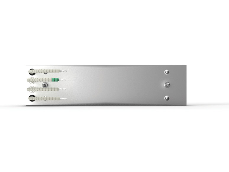
Wiring Diagram
| L + N | outer, shorter leads |
| TE + (NiCr) | inner, longer leads with green marking |
| TE - (Ni) | inner, longer leads without marking |
Mounting of Ceramic Radiators / Installation in Reflectors
- Our ceramic terminal pillar is an integral part of the heater assembly. The heater back and the terminal pillar are one single ceramic component, which enhances the bonding strength of the heater. Compliance with the specified basic strength of the terminal pillar is monitored through AQL-sampling inspection. (see video:"strength testing of ceramic terminal pillar").
- The ceramic heaters are secured in place by inserting the fastening clip without using any tool to prevent damage to the guide groove of the ceramic terminal pillar (breakage, chipping).
- In cases where device-specific heater housing or custom heating platens with multiple closely spaced ceramic elements limit mounting freedom, manual insertion of the fastening clip may be challenging. In such situations, and/or when using reflector plates with a thickness over 1 mm, reducing the wave spring height may facilitate assembly. However, make sure that the ceramic heater fits securely (see video „adjusting wave spring height").
- When laying and connecting the beaded connection wires, do not pull on them as it may cause the wire connection inside the ceramic heater to break or shift. If this happens, the heater will no longer be safe to operate and must not be used.
- Damages resulting from improper installation are not covered by warranty. To facilitate easy proof that any damage or irregularities were present upon delivery, all our ceramic heaters are wrapped in protective film.
- Install electric heating elements in systems, machines, and devices in such a way that they are easily accessible at all times and can be easily replaced if necessary. Heating elements are wear parts: they age due to temperature-related structural changes in the heating conductor material and can fail due to operational and application-related influences (e.g., thermal expansion, vibration, corrosion, contact with aggressive media) as well as due to incorrect operation or control errors. In the event of a malfunction, replacement is necessary.
- In every practice application there are working and environmental parameters which can not be calculated exactly in theory. That is why we recommend generally to test heating elements in the application under real working conditions in advance.
Operating Instructions for Quartz Cassette Heaters
Introduction
With infrared radiation from our infrared emitters, a wide variety of materials can be heated without contact. The energy transfer from the emitter to the product takes place almost immediately after switching on. This is because heat radiation, as electromagnetic radiation, is as fast as light and does not depend on "slow" transport media. Infrared emitters can therefore be used both in a vacuum and in an ambient atmosphere. The different designs and infrared wavelengths allow them to be used in a wide variety of applications.
In the case of medium-wave quartz emitters, a heating conductor heats quartz glass tubes and thus causes the glass to vibrate. Depending on the temperature, a dark red to bright orange glow can be seen.
Quartz infrared radiators have an emission spectrum comparable to ceramic radiators in the medium-wave and long-wave infrared spectrum. The difference is made by the short-wave spectral band below 3 µm, which only quartz infrared emitters have. Despite many overlaps, the application areas of both emitter types therefore differ. Due to their lower mass, quartz IR emitters have shorter response times and are thus recommended for cyclical or frequently interrupted work processes. However, quartz emitters are mechanically more fragile and for example not suitable for dusty atmospheres. Quartz infrared emitters are available as individual tubes or as cassettes. The dimensions of the cassettes follow those of the ceramic elements, so that ceramic and quartz infrared heaters can also be used in mixed arrangements in IR heating platens. For uniform installation, quartz cassettes are therefore also available with a ceramic connection socket, just like the ceramic elements.
Safety
As a manufacturer of heating elements, Freek is not responsible for the conditions in which its heating elements are installed, connected and used in the various customer-specific applications, nor is Freek responsible for how the heating elements are controlled. Rather, it is the customer's responsibility to be aware of and observe good engineering practice as it is recognised in the application and business markets in question. For example, many machines and their equipment are subject to the standard EN 60204 "Safety of machinery – Electrical equipment of machines".
Additionally, the customer is responsible for ensuring that electrical heating elements are only ever connected under the responsibility of a qualified electrician. This is because only a qualified electrician will know the risks associated with electrical heating elements, such as fire, explosion, combustion or electric shock, and – even more importantly – will know the safety measures that need to be put in place in order to prevent such events from occurring, even if the heating elements malfunction. Examples of these safety measures include protection against contact, thermal insulation, electrical insulation, temperature control, overtemperature prevention, earthing, residual current operated circuit breakers, overcurrent circuit breakers and miniature circuit breakers.
General Remarks & Handling
Risk of Overheating
- The aluminised projector/reflector or housing sheet metal used for our emitters begins to corrode at temperatures above 500°C. This causes the sheet metal to lose its reflective properties, which can result in critical overheating and thus destruction of the emitters.
- Under normal circumstances 500°C is rarely reached, even in high-power applications, due to the excellent reflective properties of the sheet metal (reflection factor ∼0.96). However, contamination, condensation, dripping water and "face-to-face" operation of radiators, reflectors, projectors, infrared platens can reduce the reflective effect and thus increase the risk of overheating.
- If these risks cannot be ruled out, we recommend using reflector plates and housings made of polished stainless steel (on request!), providing air cooling or using external temperature sensors to prevent overheating by temperature controllers.
Overcurrent
- Our infrared heaters are designed for operation at specified voltages. Any higher operating voltages differing from this can considerably reduce the lifetime or lead to immediate failure (15 % more voltage = 32 % more power!!!).
Installation Position
- The heater is designed for horizontal operation only unless clearly specified for vertical operation.
- In moving applications/fields, it must be ensured that quartz heater tubes are always mounted crosswise to the direction of movement.
- Install electric heating elements in systems, machines, and devices in such a way that they are easily accessible at all times and can be easily replaced if necessary. Heating elements are wear parts: they age due to temperature-related structural changes in the heating conductor material and can fail due to operational and application-related influences (e.g., thermal expansion, vibration, corrosion, contact with aggressive media) as well as due to incorrect operation or control errors. In the event of a malfunction, replacement is necessary.
Safety Distances
- Please ensure that you always leave sufficient space between the beaded leads of our quartz infrared heaters and the mounting or cover plates above/below them. In certain contaminated atmospheres, conductive deposits can from on surfaces which increase the risk of earth faults or short circuits.
- We recommend using a glass fibre sleeve over the beaded leads as additional touch protection measure.
- Ensure that infrared heaters cannot be touched during operation and that a safe distance to the heater is maintained so that no fires or burns can be caused by the radiation.
- The temperature of the infrared heaters can reach much higher than 600°C at the glass surface. As with all hot heat sources, it must be ensured that the atmosphere in which the heaters are operated does not contain explosive gases that could be ignited on contact with the heater surface. In all cases, the operator is responsible for ensuring that the heaters are suitable for the application.
- Due to thermal expansion, a minimum distance of 5 mm must be maintained between two heaters.
- The recommended distance between the radiant surface and the material to be heated is 100 to 200 mm.
Ventilation
- Substances that evaporate due to heat radiation can reduce the radiation power and lead to problematic deposits on leads and reflectors. Depending on the application, sufficient ventilation of the working area therefore must be provided.
Tests
- In every application, there are, in practice, working and environmental parameters which cannot be calculated exactly in theory. That is why we recommend generally testing quartz heaters in the application under real working conditions in advance.
Wiring Diagram
| L + N | outer, shorter leads |
| TE + (NiCr) | inner, longer leads without marking |
| TE - (Ni) | inner, longer leads without marking |
Operating Instructions for Quartz Halogen/Tungsten Emitters
Introduction
With infrared radiation from our infrared emitters, a wide variety of materials can be heated without contact. The energy transfer from the emitter to the product takes place almost immediately when the unit is switched on. Heat radiation as electromagnetic radiation is as fast as light and does not depend on "slow" transport media. Infrared heaters can therefore be used both in a vacuum and in an ambient atmosphere. The various designs and infrared wavelengths allow them to be used in a wide variety of applications.
Short-wave quartz heaters are the infrared heaters with the highest radiation intensity (up to 20 W/cm²). They consist of a coiled tungsten wire in a hermetically sealed quartz glass filled with inert gas. Depending on the desired emission spectrum, differently coiled heating wires are used. R7s-connections are used as standard as they are also common for halogen spotlights as light sources. Alternatively, we offer various other fastenings and connections.
The heating and cooling times are only a few seconds, which makes them ideal for applications with short cycle times that have to start quickly or cool down quickly, for example when the conveyor belt is at a standstill.
Safety
As a manufacturer of heating elements, Freek is not responsible for the conditions in which their heating elements are installed, connected and used in the various customer-specific applications, nor is Freek responsible for how the heating elements are controlled. Rather, it is the customer's responsibility to be aware of and observe good engineering practice as it is recognised in the application and business markets in question. For example, many machines and their equipment are subject to the standard EN 60204 "Safety of machinery – Electrical equipment of machines".
Additionally, the customer is responsible for ensuring that electrical heating elements are only ever connected under the responsibility of a qualified electrician. This is because only a qualified electrician will know the risks associated with electrical heating elements, such as fire, explosion, combustion or electric shock, and – even more importantly – will know the safety measures that need to be put in place in order to prevent such events from occurring, even if the heating elements malfunction. Examples of these safety measures include protection against contact, thermal insulation, electrical insulation, temperature control, overtemperature prevention, earthing, residual current operated circuit breakers, overcurrent circuit breakers and miniature circuit breakers.
General Remarks & Handling
Freek's quartz-halogen/tungsten heaters emit primarily medium-wave and short-wave infrared radiation. The output is generated by a high-temperature tungsten coil housed in a sealed quartz tube.
Quartz halogen/tungsten heaters are a very powerful heat source, so some precautions must be taken during installation and operation.
- Gloves should be worn while handling the heater. Finger prints can affect the optical properties of the glass tube and may reduce the operating life of the heater.
- If necessary, clean any dirt, oil or lint from the heater with alcohol and a lint free cloth or tissue.
- Quartz halogen heaters can produce high intensity white light which could cause damage to human eyes. Care should be taken to ensure that personnel cannot look directly at the heaters during operation. If necessary, a filter to reduce the glare or protective glasses should be provided. In such cases, personnel should be warned of the danger using suitable signage.
- The heater is designed for horizontal operation only unless clearly specified for vertical operation.
- Quartz halogen/tungsten heaters may take up to 10 times the normal operating current when operated from cold (normal room temperature). Ensure that fuses or other protective devices are correctly specified to handle high starting currents.
- In cyclical processes, complete switch-off of the heaters should be avoided, as the high currents when frequently switched on again can have a negative effect on the service lifetime. If possible, the heaters should instead be kept on stand-by at low power.
- Ensure the heater is not exposed to vibration during operation as this will also reduce operating life.
- Excessive mechanical or physical force during handling or installation could break or damage the glass tube. Broken glass may be hazardous to personnel and also the heating process.
- Always turn the electrical power off before inserting, removing or cleaning the heater.
- Ensure heaters do not radiate directly onto nearby heaters as this will increase operating temperature and reduce operating life.
- The heater should be installed by a qualified person ensuring all relevant electrical safety standards are adhered to.
- The heaters should only be used in approved fixtures designed for quartz halogen/tungsten heaters.
Risk of Overheating
- The aluminised projector/reflector or housing sheet metal used for our emitters begins to corrode at temperatures above 500°C. This causes the sheet metal to lose its reflective properties, which can result in critical overheating and thus destruction of the emitters.
- Under normal circumstances 500°C is rarely reached, even in high-power applications, due to the excellent reflective properties of the sheet metal (reflection factor ∼0.96). However, contamination, condensation, dripping water and "face-to-face" operation of radiators, reflectors, projectors, infrared platens can reduce the reflective effect and thus increase the risk of overheating.
- If these risks cannot be ruled out, we recommend using reflector plates and housings made of polished stainless steel (on request!), providing air cooling or using external temperature sensors to prevent overheating by temperature controllers.
- The heaters must be protected by suitable measures (shielding, ventilation, sufficiently dimensioned "cold" connection length) against reaching temperatures above 300°C at the hermetically sealed flat connection ends. Otherwise the seal may be damaged, resulting in the immediate destruction of the radiators.
- When operating in a (partial) vacuum, the external convective air cooling is hardly present, if at all. The risk of critical overheating of the hermetically sealed flat connection ends is greater as a result. To minimise the risk of overheating, we therefore recommend not using standard radiators but instead dimensioning the cold connection ends longer. If standard emitters with "cold" standard connection length fail in applications in (partial) vacuum due to overheating of the connection ends, this is the sole responsibility of the customer.
- Ensure the temperature of the glass tube does not exceed 800°C.
- Ensure the heaters are operated at a safe distance from combustible materials.
Overcurrent
- Our infrared heaters are designed for operation at specified voltages. Any higher operating voltages differing from this can considerably reduce the lifetime or lead to immediate failure (15 % more voltage = 32 % more power!!!).
Installation Position
- The heater is designed for horizontal operation only unless clearly specified for vertical operation.
- In moving applications/fields, it must be ensured that quartz heater tubes are always mounted crosswise to the direction of movement.
- Install electric heating elements in systems, machines, and devices in such a way that they are easily accessible at all times and can be easily replaced if necessary. Heating elements are wear parts: they age due to temperature-related structural changes in the heating conductor material and can fail due to operational and application-related influences (e.g., thermal expansion, vibration, corrosion, contact with aggressive media) as well as due to incorrect operation or control errors. In the event of a malfunction, replacement is necessary.
Safety Distances
- Ensure that infrared heaters cannot be touched during operation and that a safe distance to the heater is maintained so that no fires or burns can be caused by the radiation.
- The temperature of the infrared heaters can reach much higher than 600°C at the glass surface. As with all hot heat sources, it must be ensured that the atmosphere in which the heaters are operated does not contain explosive gases that could be ignited on contact with the heater surface. In all cases, the operator is responsible for ensuring that the heaters are suitable for the application.
- Due to thermal expansion, a minimum distance of 5 mm must be maintained between two heater units (halogen heater in reflector).
- The recommended distance between the radiant surface and the material to be heated is 100 to 200 mm.
Ventilation
- Substances that evaporate due to heat radiation can reduce the radiation power and lead to problematic deposits on leads and reflectors. Depending on the application, sufficient ventilation of the working area therefore must be provided.
Tests
- In every application, there are, in practice, working and environmental parameters which cannot be calculated exactly in theory. That is why we recommend generally to test cartridge heaters in the application under real working conditions in advance.
Infrared Research
In order to shed light on the darkness of the "infrared half-truths", our cooperation partner Ceramicx Ireland developed the Herschel measuring robot in close cooperation with Trinity College Dublin and presented it as a world first at the K trade fair in Düsseldorf in 2013 (Ceramicx Center for Infrared Innovation (C²I²) ). Herschel can scan and visualize 3D images of a the heat flux that is radiated from any IR source. This unique ability is of inestimable value for the constructive and material design (material properties) and optimization of the infrared heating elements themselves (element design), as well as infrared ovens, IR heating platens and infrared heating devices of all kinds (solution design).
-
 download pdf
Heatworks 11 - The proof of the pudding - The new Ceramicx Centre for Infrared Innovation
(Dr Gerard McGranaghan. In: HeatWorks 11, February 2014, pages 12 - 14; Publisher: Ceramicx Ireland Ltd.In this article you are introduced to the Ceramicx Center for Infrared Innovation C²I². This supports Ceramicx to unveil the truth about infrared heating and its industrial heat works applications. To achieve this goal a group of scientists takes advantage of the Herschel measuring robot that allows for mapping 3D heat flux images of any kind of IR radiating sources. Additionally the Center also imparts knowledge of IR-radiators and their applications via its online courses on www.ceramicxinfraredtraining.com.
-
 download pdf
3D Infra-Red Heat Flux Mapping
This technical article explains the most intriguing "toy" of the Ceramicx Centre of Infrared Innovation C²I², the Herschel measuring robot. With Herschel it becomes possible to scan 3D images of a the heat flux that is radiated from any IR source. Herschel indeed is an instrument that makes IR-radiation visible. This will help to lift IR applications engineering onto the next performance level.
-
 download pdf
CCII 00146 - Performance evaluation of 800W FTE, FFEH, and Black FFEH
In this experimental study the performance of three standard Ceramicx elements, an 800W FTE, an 800W FFEH, and an 800W FFEH with black glaze was evaluated within Ceramicx' Herschel heat flux robot. From the results it is calculated that the FFEH outperforms the FTE by 9.2%, and the black glaze outperforms the white glaze by 3.9%.
-
 download pdf
CCII 00120 - Comparison of aged reflector efficiency
As previously shown by Ceramicx, the use of a polished aluminised steel reflector increases the percentage radiative heat flux emitted towards the heating target compared with stainless steel. For lower temperature applications, where oxidation of the aluminium is unlikely to occur, aluminised steel is shown to be a better performing material. For higher temperature applications, where aluminium oxidation is likely to occur, stainless steel is a better choice as it leads to a greater proportion of radiative energy directed towards the target material.
-
download pdf
CCII 00117 Aluminised steel comparison
The exact reasons for the material degradation differences are unknown; however, this analysis shows that at elevated temperatures, the durability of the aluminised steel material used by Ceramicx is superior to that used by a leading competitor. The influence of the surface polishing of the Ceramicx material cannot be discounted, however quite how this influences the thermal durability is unknown.
-
download pdf
CCII 00116 Analysis of the performance change by inclusion of Basalt fibres in Ceramic Elements
This analysis shows that adaptation of Ceramicx's ceramic mixture to include igneous rock fibres does not alter the efficiency of the elements. Of more influence is the colour of the glaze, which can lead to a 4% increase in the radiant heat flux output for a 1000W heater. Consistent with previous research carried out and published by Ceramicx, the black glaze remains the most efficient heat flux increase method.
-
download pdf
CCII 00107 Comparison study of five quartz glasses used for heating element protection
The results of the experiment above show that the Robax® glass, currently used by Ceramicx, to protect its heaters possesses one of the best IR transmission properties for the quartz cassette heaters. This is because the transmission spectrum for this glass is at a maximum in the active waveband of the heater.
-
 download pdf
CCII 00014 Aluminised and Stainless Steel Discolouration
This test report shows the superiority of the Ceramicx reflector material compared to alternatively used reflector materials regarding its resistivity against high temperature discolouration and degeneration, both leading to an inevitable loss of reflection properties. Also in a direct comparison to a well-known European competitor it shows that Ceramicx' material is at least equivalent if not even better.
-
 pdf downloaden
CCII 00007 black vs white glaze & CX vs EU Competitor
This evaluation provides evidence for the superior performance of the black emitter surface over the white surface. In fact the results find the black element outperforming the white by 8%. A second set of tests shows for a range of black and white hollow emitters that performance of Ceramicx' and EU Competitor's modules are almost identical in performance.
-
download pdf
CCII 00146 - Performance evaluation of 800W FTE, FFEH, and Black FFEH
In this experimental study the performance of three standard Ceramicx elements, an 800W FTE, an 800W FFEH, and an 800W FFEH with black glaze was evaluated within Ceramicx' Herschel heat flux robot. From the results it is calculated that the FFEH outperforms the FTE by 9.2%, and the black glaze outperforms the white glaze by 3.9%.
-
 download pdf
CCII 00034 Performance of Hollow vs Plain elements, with and without reflector
This report measures the differences in emitted heat flux between hollow and plain elements. Of particular interest is the effect of a reflector placed at the rear of the elements on the emitted infrared output. If a hollow element is used without a reflector, it will not suffer a drop in performance to the same extent as using an FTE element without a reflector. The FFEH 600W gives almost the same infrared output as an FTE 650W element, and also a higher peak heat flux thanks to its narrower elliptical heat flux profile.
-
 download pdf
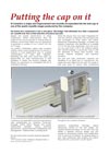
Heatworks 11 - Putting the cap on it
(In: HeatWorks 11, February 2014, pages 14 - 15; Publisher: Ceramicx Ireland Ltd.)This article explains the motivation, the procedure and the detailed realization of a significant further improvement of the Ceramicx' quartz cassette heater range. After reading the article you will understand why Ceramicx customers can only benefit from this innovation.
-
 pdf downloaden
IR v Convection Report V2
This paper proves by the sample of an aerospace grade carbon fibre laminate of approximately 4, 5 mm thickness that IR out-of-autoclave (OOA) curing has an ability to greatly enhance composite properties compared to the results achieved in a conventional convection oven. It has been shown that cure using a convection oven is not a fit and forget method with programmed heating rates not being representative of the heating rate that the part experiences. IR's ability to respond rapidly to temperature variation ensures a greatly enhanced ability to match part temperature to intended temperature.
-
 pdf downloaden
CCII 00152 - IRP4 performance evaluation
Two tests were implemented for the purpose of this report:
Test 1 compares the performance of 2 standard FFEH 800W (running at 400W each) when paired with various reflectors, and in turn when fitted with various grills as seen in an IRP4.
Test 2 quantifies the ability of an IRP4 to heat a concrete slab from a set distance. It also monitors the internal and surface temperatures of the IRP4. In fact, the aluminised steel reflector outperforms the stainless steel by approximately 6% and using a grill means a performance reduction by min. 20%. -
 pdf downloaden
CCII 00129 - Post-cure carbon fibre heating with various elements
A company is interested in heating the surface of a post-cure composite piece. The piece needs to be heated to approximately 230°C within 15 seconds. This paper demonstrates the procedure to find the best suiting emitter type and IR heating set-up to match the heating task.
-
download pdf
CCII 00101 Infrared heating of multiwalled composites and polymers
The results presented in this paper are indicative of the surface heating and penetrative capability of infrared. This data shows that simple material variations such as surface finish can cause dramatic changes in the IR the heating rate as well as how the penetrative properties of infrared radiation, when matched to the material being heated can often be utilised to heat a second surface below the first layer. The results also show the importance of actual tests on specific materials which must be taken in conjunction with the material processing steps.
-
download pdf
CCII 00034 Performance of Hollow vs Plain elements, with and without reflector
This report measures the differences in emitted heat flux between hollow and plain elements. Of particular interest is the effect of a reflector placed at the rear of the elements on the emitted infrared output. If a hollow element is used without a reflector, it will not suffer a drop in performance to the same extent as using an FTE element without a reflector. The FFEH 600W gives almost the same infrared output as an FTE 650W element, and also a higher peak heat flux thanks to its narrower elliptical heat flux profile.
-
 download pdf
CCII 00024 Report for Friedr Freek QFE Arrays
This test report analyzes the heat flux homogenity respectively profile of emitter arrays in IR modules or panels, specially looking at the effect of reflectors and contribution of single emitters. An array comprising 9 QFE 150W elements arranged in a 3 x 3 pattern was tested with and without surrounding reflectors. In addition various single elements were powered off to study the heat flux profiles. Using the longest reflector minimises dispersion of the emitted radiation and also results in a more confined heat flux spread with higher peak values.
Downloads:
-
Flyer - Looking for contactless heating?

Freek offers long-wave, medium-wave und short-wave infrared emitters!
-
Really hot! Our Product Flyer.
Download our leaflet here.