IR heat measurement - The game has changed! - 26.09.2013
Thanks to hard work, innovative thinking and Enterprise Ireland (EI) Innovation Partnership funding,
Ceramicx and Trinity College Dublin (TCD) are now ready with a new way of measuring and reading the Infrared heating spectrum
(Adrian Lunney. In: HeatWorks 10, September 2013, pages 1 - 3; Publisher: Ceramicx Ireland Ltd.)
 The characteristics of the heat of IR heat radiation has sometimes been described as 'sunshine without light' indeed the scientific literature
on heat to date constantly refers to formulae and methods involving 'black bodies'.
The characteristics of the heat of IR heat radiation has sometimes been described as 'sunshine without light' indeed the scientific literature
on heat to date constantly refers to formulae and methods involving 'black bodies'.
Now a little more light has entered the picture. Ceramicx and TCD have developed a high quality machine tool that will offer a predictive Infrared energy science; a new instrument that will be invaluable in designing both manufacturing processes and thermalbased manufacturing machinery.
Ceramicx expects to use it immediately in the design and performance of its own IR components, the assessment of competitor materials and in enabling design for those building machines involving IR heatwork. The machine will focus on measuring infrared energy produced and the best application of this energy for the correct heatwork solution for our customers.
This kind of IR heat research is actually essential for industry and our sustainable future since it precisely maps the energy required to perform the required heating of the target body compared with the energy required to produce the heat at the source.
In short our IR heating machine tool is on spec and on schedule for delivery to Düsseldorf Germany in good time for our exhibiting presence at the triennial plastics exhibition K 2013, October 16th-23rd.
The new science of IR heat measurement
Ceramicx and Trinity College Dublin (TCD) have worked hard together in order to establish IR energy
and heat measurement principles and hardware that will both stand the test of time and sustain further developments.
HeatWorks magazine asked Dr. Tony Robinson, TCD, and Ceramicx partner in the EI Innovation project, to run the rule over the new measurement system.
Heat flux transducers are a key part of achieving what we do in this work. This equipment is a sensor that measures a change in temperature over a certain distance and uses the geometry and the thermal properties of the material within this distance to calculate the heat flux. For example, a radiometer acts as a differential thermocouple measuring the temperature differential between the centre and the circumference of a thin circular foil disk. This disk is generally made of metal, such as Constantan, and it is bonded to a circular opening in a cylindrical copper heat sink. As the thermal properties of the metal are known it is possible to relate the output voltage from the transducer to a heat flux value via the calibration data provided by the manufacturer.
IR transparent windows can be placed in front of the heat flux sensor to block out the convective heat flux reaching the sensor such that only the radiant heat flux energy is measured. The material used in the window will determine the radiation bandwidth that reaches the sensor.
The heat output from radiant heaters is generally characterized by the total output power and some form of heat map. To find the total output power, a heat flux sensor is used in order to scan a plane or a hemisphere in front of the heater: The advantage of using a hemispherical test area is that a smaller test rig can be used while ensuring that the total radiant heat energy from the heater is bounded within the test area. A heat flux curve can then be plotted from the obtained data points and via interpolation, the total output power is then determined by integrating under the resulting curve.
If measurements are to be taken over a large physical space and done so with high spatial resolution it is essential that the measurement system be automated. This is particularly true for cases, such as the Ceramicx/TCD measurement tool where the technology is to be used in an industrial setting. To this end, a new infrared heat flux measurement and mapping system is being developed which also uses a robot in combination with a linear stage to position an IR heat flux sensor at fixed grid locations in 3D space in front of a heater assembly. The entire controls and positioning system along with the data acquisition are controlled with the LabView programme and the data is post processed in the Matlab programme.
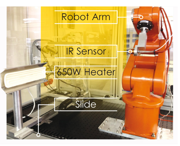
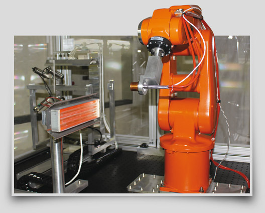
A photographic idea of the IR heat flux mapping apparatus is shown here in Figure 1. A full trough ceramic heater element manufactured by Ceramicx Ltd is mounted on an SMS rolled screw, twin-bearing linear stage with a total travel of approximately 630 mm. The heater is rated at 650W and has an Aluminised steel reflector situated behind it to redirect a portion of the heat which would otherwise be lost through the back. The heater has an embedded K-type thermocouple and is powered by an Elektro-Automatik PS 8000T, 0-360 V, 0-10 A DC power supply.
The sensor is a Medtherm Schmidt-Boelter Thermopile Heat Flux Transducer with a design maximum heat flux level of 2.3 W/cm². The sensor is designed for measuring up to 20 W/cm². The sensor comes as standard without any window attachments, in this configuration it is a "total" heat flux transducer that measures the sum of the convective and radiant heat flux. It is not designed to measure conduction heat transfer. When a window of a specific spectral transmittance passband is attached to the sensor, the incident radiant heat flux is measured. In this case, a Barium Fluoride window is attached to the sensor meaning IR in the band 0.4-10 micrometres is measured. The Schmidt-Boelter thermopile sensor generates a millivolt output directly proportional to the net absorbed heat transfer rate to the thermopile sensing element.
Similar Medtherm Schmidt-Boelter thermopile transducers are used in wind tunnel testing, fire testing, rocket engine testing, and are qualified for the Space Shuttle and other flight programs as well as heat flux standards for flammability testing on many ASTM and ISO test specifications.
The primary aim of course of our new system is to measure the radiant heat flux distribution from the heater system. This is so that its footprint can be determined with regard to heating of a materials target such as the plastic sheet used in a thermoforming process. Further to this, this will also allow the radiant efficiency to be determined as well as how different heater and reflector designs change the radiant heat flux distribution. To this end, the heater and sensor is mounted on positioning systems so that a heat flux map can be created in a space of 500 mm x 500 mm x 500 mm.
An ABB IRB-120 6-axis robot is used to position the sensor in front of the infrared heater assembly. The robot has the capacity to cover the required width and depth (500 mm x 500 mm) plane parallel to the front plane of the heater, however it can only cover a length of 100 mm from the heater. In order to increase the length, the heater is mounted on the SMS twin-bearing linear stage which then increases the total possible length to 500 mm.
The measurement system requires that the robot and linear stage be controlled so as to position the sensor in a specified location in front of the heater after which one or more IR heat flux measures is acquired. The relative position and the magnitude of the sensor output voltage must then be stored for future post processing.
The user operated PC is connected directly to the IRC-5 robot controller, the LabView system administrates the operation of the robot and the data recorded from each of the thermocouples and heat flux sensors.
When the program within the robot controller is initiated, the robot arm defaults to a specified 'Home' position. In the LabView interface, a designated grid size is defined, along with the number of data points to be recorded, the distance between these data points and the number of grids to be executed.
Once these parameters have been set, the LabView system sends a connection signal to the robot controller to set up position through a LabView system loop. The data acquisition system is then triggered and the desired information is recorded from each of the sensors about the system.
When the data acquisition is completed, LabView generates the next target for the robot to move to, and the loop continues. At the end of a complete grid, the robot arm is signalled by the controller to move back to the 'Home' position while the linear stage is activated and traverses back to its next position. The linear stage is activated a number of times and is defined by the user depending on the resolution desired. When each of the grids is completed, the data is saved and the robot is moved to a safe position out of the way of the rest of the equipment to allow adjustment to be made on the test bed. Once the doors to the rig are opened the motors to the robot are automatically disengaged, allowing safe access to the rest of the test bench.
Thus far, our new system has been validated using the following tests. It should be noted however that the sample sizes are still relatively small.
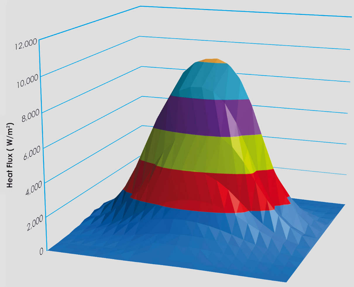
Figure 2, for example shows a sample radiant heat flux map for a 500 mm x 500 mm vertical plane located 100 mm centrally in front of the heater. The heater power was 800W for this particular test. The graph indicates that for this particular test, the radiant heat flux distribution is parabolic in shape with a concentrated zone in the centre in proximity to the heater element itself. The peak heat flux in this region is 10184 W/m² . Moving away from the central region, and thus the heater, the heat flux distribution drops off rapidly, being as low as 80 W/m² at a location 250 mm above the geometric centre of the heater.
These simple enough measurements can be immensely helpful to designers of industrial processes. For example, the magnitude of the radiant heat flux, as well as its distribution, is an important parameter in industrial process, such as heat treatment and thermoforming, since heater elements are often used in arrays. Information such as that provided below will aid in the design of the arrays whereby the quantity and uniformity of the impinging infrared radiation on a target can be assessed.
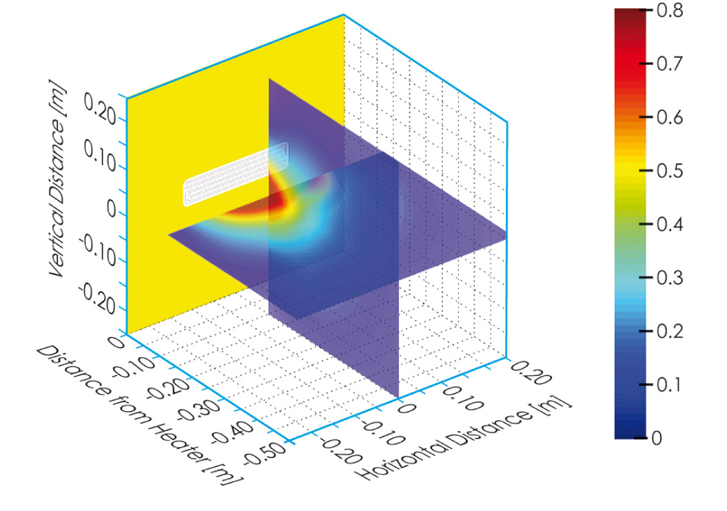
Figure 3a illustrates the 3 dimensional mapping of the radiant heat flux within a 500 mm x 500 mm x500 mm region of space. The left figure shows cross planes of the radiant heat flux distributions at distances of 100 mm to 500 mm from the heater surface. Since infrared radiation diffuses in all directions, it appears as a spreading of the radiant heat flux, in the sense that the magnitude of the heat flux diminishes with distance from the source as does the steepness of the local profile. This is better illustrated in figure 3(b) which plots the IR received by the sensor as a percentage of the heater input power. The orange plot illustrates how the percentage radiant heat flux emitted from a typical white FFEH element diminishes with distance from the heater assembly. The red plot represents the equivalent black FFEH element and shows clearly how the 3D IR mapping tool can measure differences in performance.
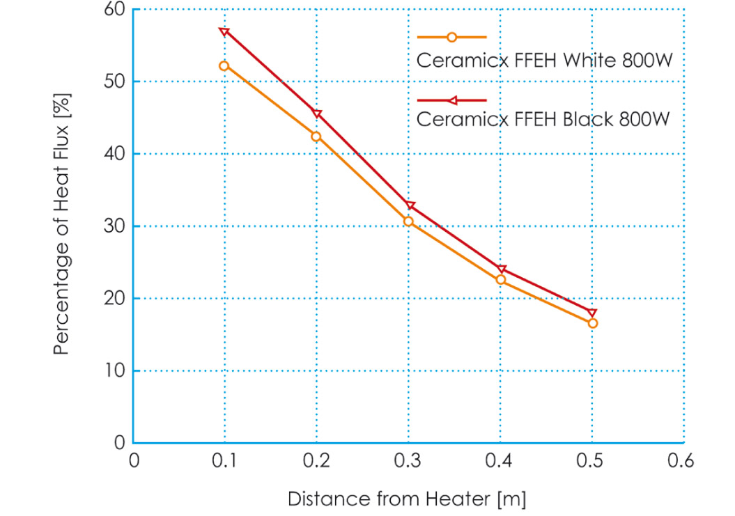
Again, knowledge of the 3D radiant heat flux profile such as this is crucial for the design of most IR heater systems. These kinds of empirical measurement give an accurate and direct measure of the quantity and evenness of the radiation on a target. These measurements also help inform decisions regarding the heater assembly design as well as the positioning of the target.
Thus far, and in scientific terms, the preliminary results of our new system have shown the viability of the technique. Measurements have been obtained which quantify the magnitude and spread of radiant heat from a source. Future work will include using more complex measurement topologies such as a hemisphere in front and behind the heater assembly so that the radiant efficiency of the heater can be determined.
Read the article on pages 1 - 3 in the 10. "HeatWorks" issue here.
older article newer article